6.3 -
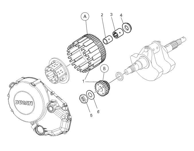
Clutch assembly: primary drive gears
1
Clutch drum/Primary drive gears
2
Inner ring
3
Inner bearing
4
Spacer
5
Threaded ringnut
6
Lock washer
Spare parts catalogue
796
CLUTCH
796
CONNECTING RODS
796 ABS
CLUTCH
796 ABS
CONNECTING RODS
Important
Bold reference numbers in this section identify parts not shown in the figures alongside the text, but
which can be found in the exploded view diagram.
Removal of the primary drive gear
Operations
Section reference
Drain the engine oil
4 - 3,
Changing the engine oil and filter cartridge
Disconnect the oil pressure sensor
6 - 5,
Checking the indicating devices
Remove the clutch cover
9 - 6.2,
Removal of the clutch cover
Remove the clutch assembly
9 - 6.1,
Removal of the APTC clutch
Remove the oil pump
9 - 2.1,
Removal of the oil pump
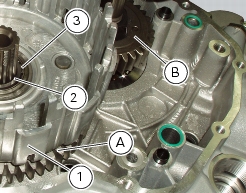
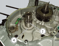
Withdraw the clutch drum (1) complete with roller bearings (3) and the driven gear of the primary gear pair (A).
Remove the circlip (2) and the internal spacer (4).
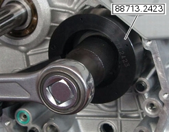
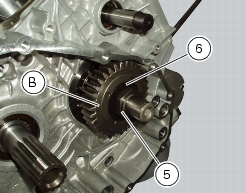
Straighten out the lock washer (6) on the nut (5) securing the primary driving gear (B).
Restrain the primary driving gear (B) using service wrench no.
88713.2423
and unscrew the threaded nut (5) securing the pinion.
Remove the nut (5) and lockwasher (6).
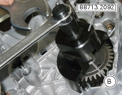
Remove the primary driving gear (B) using puller
88713.2092
and interposing a packing piece of aluminium or copper between the crankshaft and the screw of the puller.
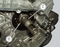
Take care to recover the key (C) from the crankshaft and the internal spacer.
Refitting the primary drive gears and checking backlash
Fully degrease the crankshaft splined end and the corresponding spline on the primary drive gear.
Check that the key (C) and internal spacer (D) are in position on the crankshaft.
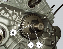
Fit the driving gear (B) onto the crankshaft with the oil pump drive sprocket facing the crankcase.
Temporarily secure the gear with the washer (6) and nut (5).
Important
If fitting a new primary driving gear (B), check the backlash.
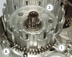
To check the gear backlash, temporarily fit the clutch drum (1) complete with internal spacer (
4
), driven gear (A), roller bearing (3) and internal bush (2) on the gearbox primary shaft. Fix a dial gauge to the engine crankcase, positioning the stylus against a gear tooth.
Turn the driven gear (A) to mesh the teeth and check with the dial gauge that backlash ranges between
0.05
and
0.07
mm.
Repeat the check at 16
different points of the driven gear.
If the measured values are outside the permissible tolerance limits, try changing the position of driven gear (A) on the primary
shaft, leaving the driving gear (B) on the crankshaft. If the backlash is still outside the tolerance limits, renew the primary drive gear pair (1).
After checking the gear backlash, secure the pinion (B) with the service tool part no
.
88713.2423
, apply the recommended grease to the ring nut (5) and tighten it to a torque of 190 Nm (Min. 171 Nm - Max. 209 Nm) (Sect. 3 - 3,
Engine torque settings
).
Stake the lock washer (6) onto the nut (5).
Refit the oil pump and check the clearance between the oil pump gear and primary drive gear on the crankshaft (Sect.
9 - 2.1,
Refitting the oil pump
).
Thoroughly degrease the mating surfaces of the clutch drum (1), the internal bearing (3) and the bush (2).
Fit the internal spacer (4) to the input shaft with its flat side facing outwards. Install the inner bush (2) and clutch drum (1)
with driven gear (A) complete with roller bearing (3).
Operations
Section reference
Refit the complete clutch assembly
9 - 6.1,
Refitting the APTC clutch
Refit the clutch cover
9 - 6.2,
Refitting the clutch cover
Connect the oil pressure sensor
6 - 5,
Checking the indicating devices
Refill the engine with oil
4 - 3,
Changing the engine oil and filter cartridge