|
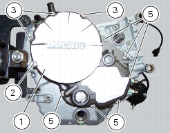
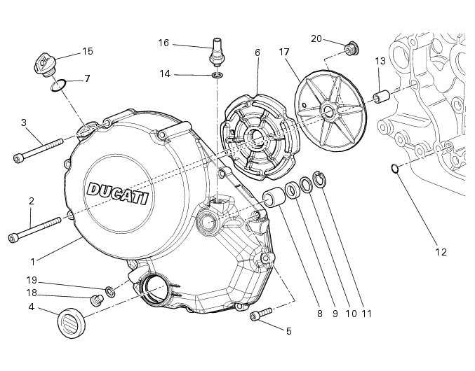
2
|
|
3
|
|
5
|
|
7
|
|
8
|
|
10
|
|
11
|
|
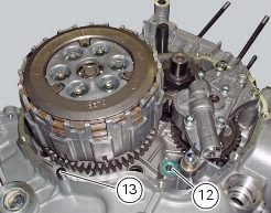
12
|
|
15
|
|
17
|
|
18
|
|
20
|
|
Disconnect the oil pressure sensor
|