6 -
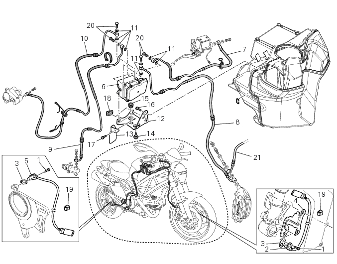
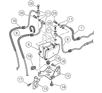
System components
1
Screw
2
ABS / speed sensor (Front)
3
Sealing washer
4
ABS / speed sensor mount (Front)
5
Speed sensor / ABS (Rear)
6
ABS control unit
7
Front pump - control unit pipe
8
Control unit - front calliper pipe
9
Rear pump - control unit pipe
10
Control unit - rear calliper pipe
11
Sealing washer
12
Support (ABS)
13
Bracket
14
(Lower) Rubber block
15
(Upper) Rubber block
16
Screw
17
Screw
18
Rubber pad
19
Guide
20
Special screws
21
Front brake hose
Spare parts catalogue
796 ABS
ANTILOCK BRAKING SYSTEM (ABS)
Important
Bold reference numbers in this section identify parts not shown in the figures alongside the text, but
which can be found in the exploded view diagram.
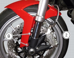
Replacing the front phonic wheel sensor
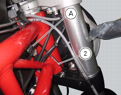
Disconnect the front ABS sensor (2) connector (A) from the main electric wiring.
Open all the retainer clamps of the front ABS sensor cable (2): refer to the tables in Sect.
7 - 6,
Flexible wiring/hoses positioning
.
Remove the front mudguard (Sect. 5 - 4,
Removal of the front mudguard
) and remove the speed sensor mounting bracket (4): the bracket is fastened by the two screws (B) retaining the front mudguard (left-hand side).
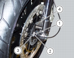
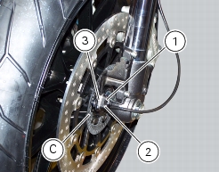
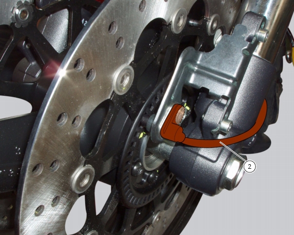
Loosen retaining screw (1) and remove the front ABS sensor (2) with calibrated gasket (3).
Before refitting, make sure that the contact parts between the front ABS sensor (2) and its seat on mounting bracket (4) are not
damaged and are perfectly clean.
Fit the new front ABS sensor (2) on the bracket (4)
.
Check the air gap between the front ABS sensor (2) and the front phonic wheel (C) as indicated in Sect. 7 - 7,
Adjusting of the AIR-GAP phonic wheel sensor
.
Fix the bracket (4) with sensor onto fork leg with the screw (1) and tighten it to a torque of 7 Nm ±10% (Sect.
3 - 3,
Frame torque settings
) then refit the front mudguard (Sect. 5 - 4,
Refitting the front mudguard
).
Connect the connector (A) to the main wiring.
Restore all the retainer clamps of the front ABS sensor cable (2): refer to table of Sect. 7 - 6,
Flexible wiring/hoses positioning
.
Replacing the rear phonic wheel sensor
Remove the right-hand footrest bracket (Sect. 7
- 15,
Removal of the footrest brackets
).
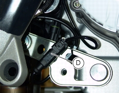
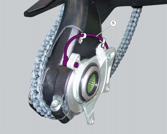
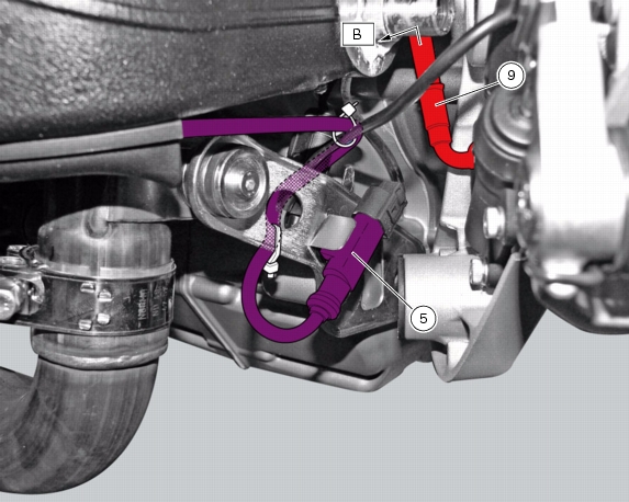
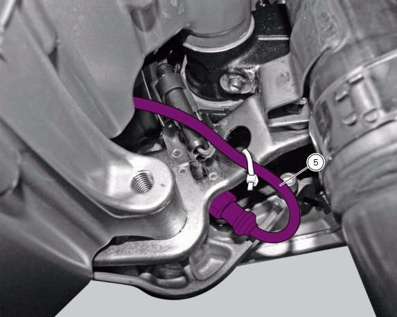
Disconnect the rear ABS sensor (5) connector (D) from the main electric wiring.
Open all the retainer clamps of the rear ABS sensor cable (5): refer to table of Sect. 7 - 6,
Flexible wiring/hoses positioning
.
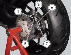
Remove the rear ABS sensor (5) from its seat on the rear calliper mounting bracket (7), undoing the fixing screw (1) and collect
the calibrated gasket (3).
Check the air gap between the new rear ABS sensor (5) and the rear phonic wheel (E) as indicated in Sect. 7 - 7,
Adjusting of the AIR-GAP phonic wheel sensor
.
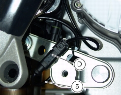
Fix the sensor to the calliper holder bracket tightening the screw (1) to the specified torque (Sect.
3 - 3,
Frame torque settings
).
Connect the connector (D) to the main wiring.
Restore all the retainer clamps of the rear ABS sensor cable (5): refer to table of Sect. 7 - 6,
Flexible wiring/hoses positioning
.
Refit the right-hand footrest bracket (Sect. 7
- 15,
Refitting the footrest brackets
).
Removing of the ABS control unit
Operations
Section reference
Remove the seat
5 - 3,
Removal of the seat
Remove the fuel tank
8 - 2,
Removal of the fuel tank
Drain the brake fluid in the pipes disconnecting these from the cylinder and from the calliper (Sect. 4 - 3,
Draining the brake circuit
).
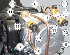
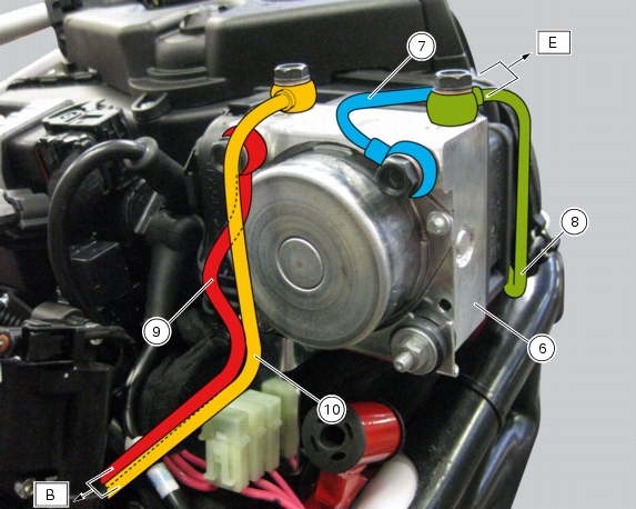
Loosen the four special screws (20) securing the pipes (10), (9), (8) and (7), on the ABS control unit (6), eliminating the gaskets
(11).
Warning
Every time that gaskets (11) are removed, they must be replaced with new gaskets (11).
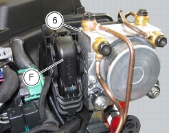
Disconnect the connector (F) from the ABS control unit (6).
Remove the ABS control unit (6).
Important
Do not open the ABS control unit: if it is faulty, replace it.
Note
Should it be necessary to replace one or more hoses, follow the procedure outlines in the paragraph “
Flexible wiring/hoses positioning
“ to determine the hose routing on the vehicle.
Refitting the ABS control unit
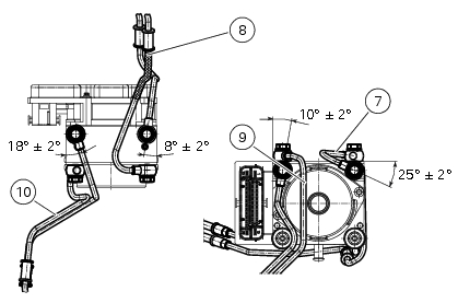
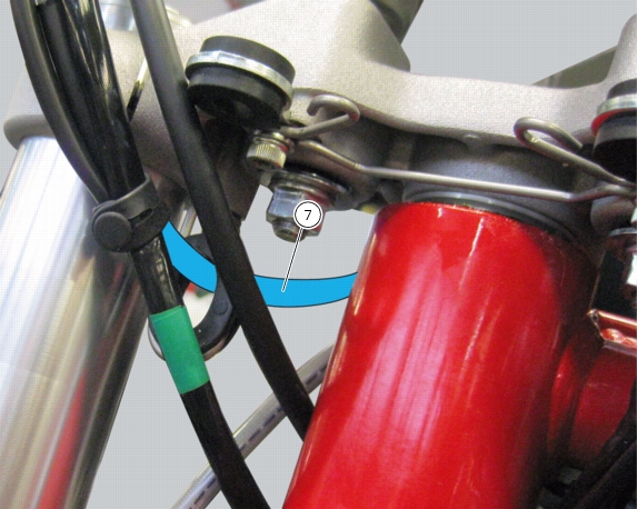
When refitting the system, pay attention to the orientation of the couplings of the hoses (7), (8), (9) and (10).
Warning
If incorrectly positioned, the hose can affect brake operation and foul moving parts.
Position the hose as shown in the figure.
Refitting is the reverse of removal.
In particular, use a new gasket set (11) and tighten the screws (23) to a torque of 23 Nm ±10% (Sect.
3 - 3,
Frame torque settings
).
To fill up the system, carry out the instructions for replacement of fluid of the pump or calliper to which the pipe is connected
(Sect. 4 - 3,
Filling the brake system with fluid
).
Important
If the ABS control unit is replaced, this must be supplied with secondary circuit already full of fluid; the control unit must be fitted
and the system filled and bled as a traditional system.
Operations
Section reference
Refit the fuel tank
8 - 2,
Refitting the fuel tank
Refit the seat
5 - 3,
Refitting the seat
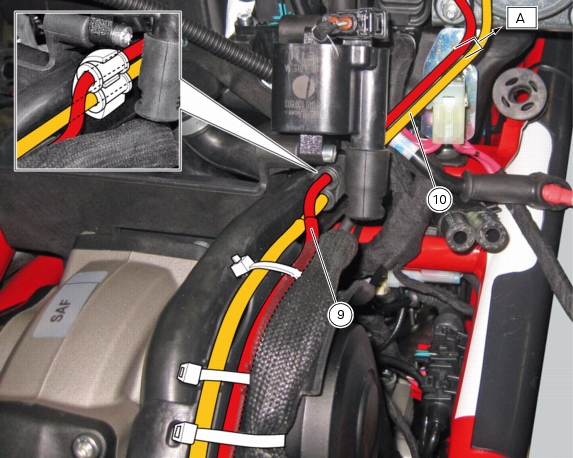
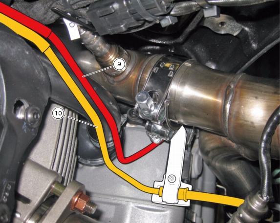
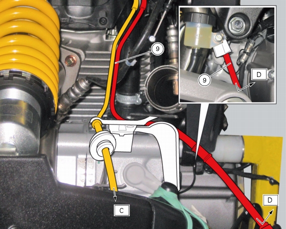
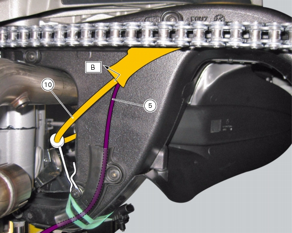
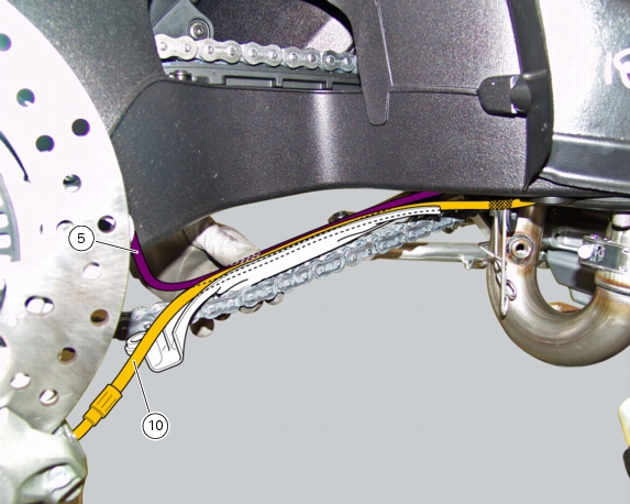
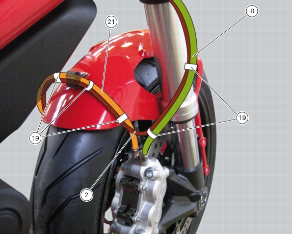
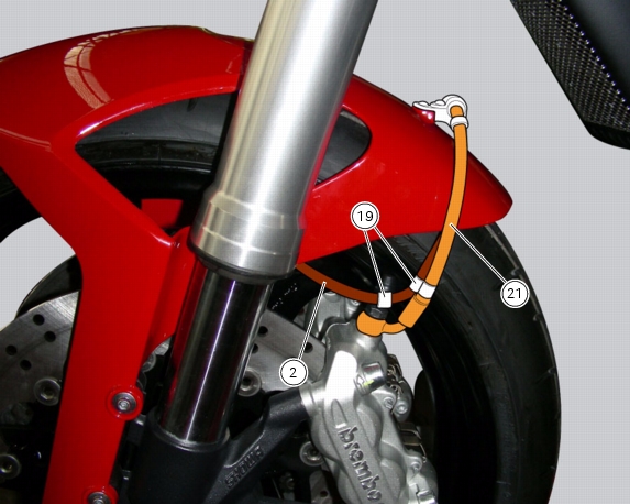
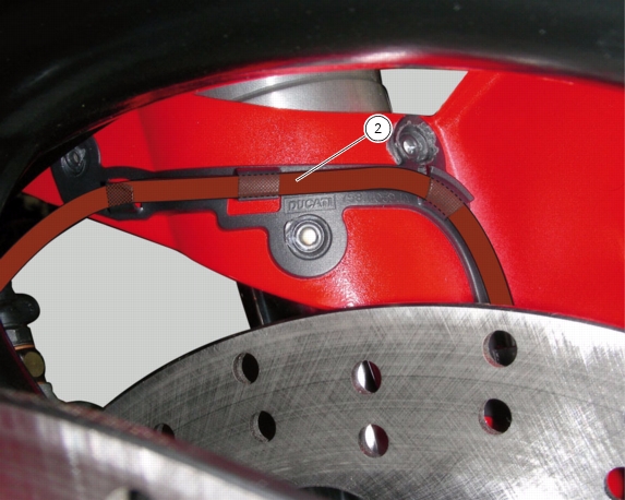
Flexible wiring/hoses positioning
The routing of the ABS wiring has been optimised to ensure the minimum obstruction.
Each section is designed to prevent interference with parts that might damage wires or cause operating failures when riding.
Table
Position
Description
Table E
-
Table F
2
ABS / speed sensor (Front)
Table C
-
Table D
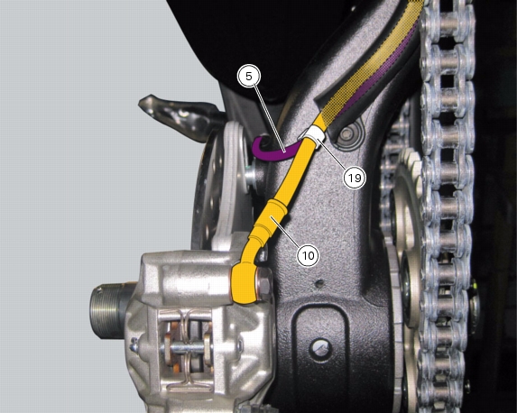
5
Speed sensor / ABS (Rear)
Table A
6
ABS control unit
Table A
-
Table E
7
Front pump - control unit pipe
Table A
-
Table E
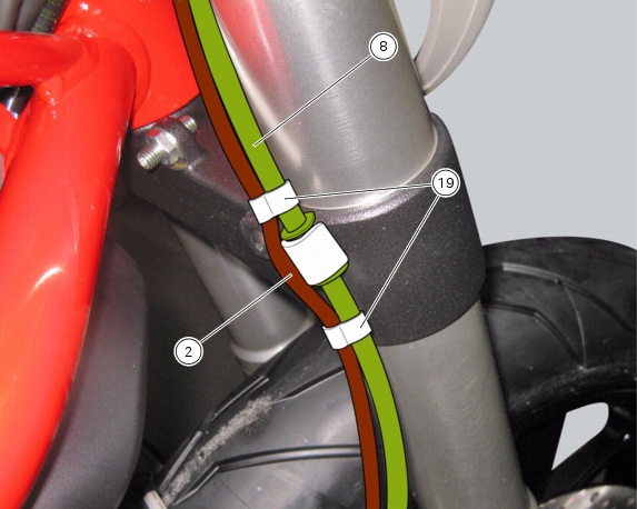
8
Control unit - front calliper pipe
Table A
-
Table B
-
Table D
9
Rear pump - control unit pipe
Table A
-
Table B
-
Table C
10
Control unit - rear calliper pipe
Table C
-
Table E
-
Table F
19
Hose clip
Table E
-
Table F
21
Front brake hose
Table
A
Table
B
Table
C
Table
D
Table
E
Table
F
1