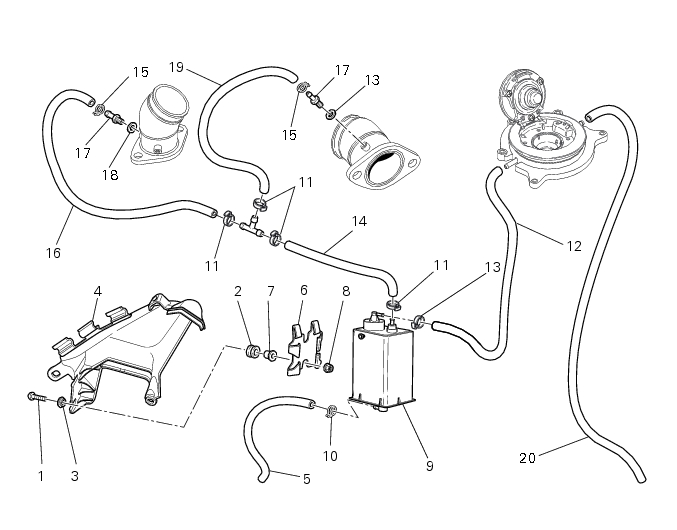
10 -
1
2
3
4
5
6
7
8
9
10
11
12
13
14
15
16
17
18
19
20
 Spare parts catalogue
Important
Bold reference numbers in this section identify parts not shown in the figures alongside the text. Refer to the exploded view diagram.
Evaporative emissions canister system (USA versions only)
USA models are equipped with an additional system with an evaporative emissions canister that prevents fuel fumes from being discharged into the atmosphere.
The hose (12) is connected to the evaporative emissions canister (9); when the fuel has been filtered, it is returned with the hose (14) to the intake manifolds via the hoses (16) and (14). Hoses (5) and (25) vent to the ground.
For correct positioning of the connection hoses see the pictures below.
Removal of the evaporative emissions canister
 
Disconnect the hose (12) connecting the evaporative emissions canister (9) to the fuel filler cap.
Release the hose (12) from the drain hose (20) by removing the strap (A).
Loosen the hose clamps (15) connecting the evaporative emissions canister (9) to the horizontal and vertical cylinders.
Undo the screws (B) and remove the LH air deflector (4), taking care to release the clutch hose (C) from the clips.
Remove the evaporative emissions canister (9) from the LH deflector (4) by releasing it from the plate (6).
Refitting the evaporative emissions canister
Refitting is the reverse of removal.
In particular the plate (6) that supports the canister from the LH deflector (4) was removed, refit it with the corresponding elements, tightening the nuts (8) to a torque of 8 Nm ±10% (Sect. 3-3, Frame torque settings).
Tighten the screws (B) to a torque of 8 Nm ±10% (Sect. 3 - 3, Frame torque settings).
 
Positioning the hoses, clamps and evaporative emissions canister