|
1
|
|
2
|
|
5
|
|
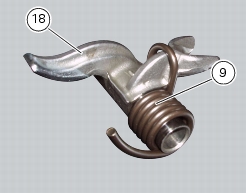
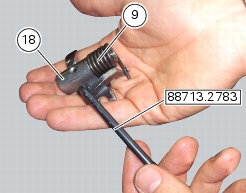
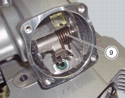
9
|
|
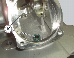
10
|
|
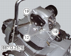
12
|
|
17
|
|
19
|
|
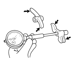
Remove the timing belts and the timing belt pulleys
|


|
-
|
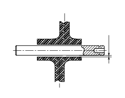
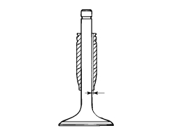
Service limit: 0.03 mm.
|


|
-
|
|
-
|