|
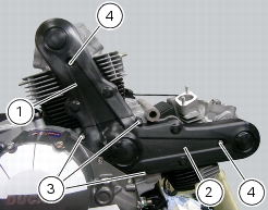
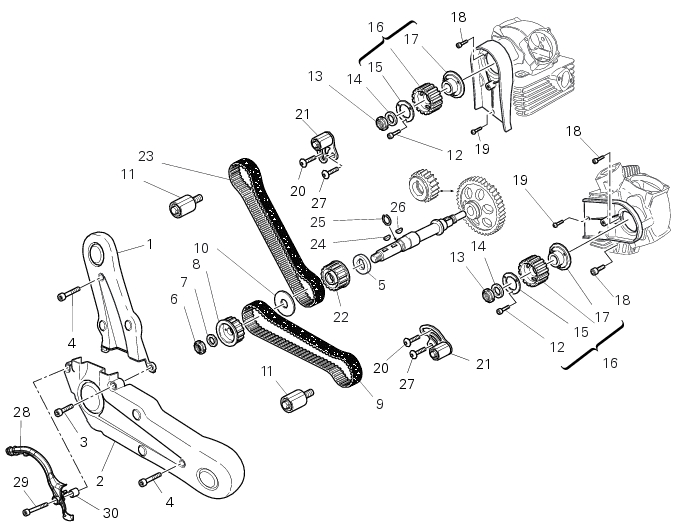
3
|
|
4
|
|
5
|
|
7
|
|
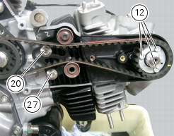
12
|
|
14
|
|
17
|
|
18
|
|
19
|
|
20
|
|
24
|
|
25
|
|
26
|
|
27
|
|
28
|
|
29
|
|
30
|