The Siemens M3C injection-ignition system is the Alfa/N type, in which the engine speed and throttle position are used as main parameters for measuring the quantity of intake air. If the quantity of air is known, the quantity of fuel can be dosed accordingly to obtain the required ratio. Other sensors in the system (engine sensor, intake air pressure, air temperature, engine temperature and lambda sensor for CO control) allow corrections to the basic management strategy to suit specific operating conditions. The engine speed and the throttle angle also make it possible to calculate the optimal advance for all types of operating conditions. The quantity of air taken in by each cylinder during each cycle depends on the density of the air in the intake manifold, the cylinder capacity and the volumetric efficiency.
Volumetric efficiency is experimentally taken onto the engine in the whole operating range (rotation speed and engine load conditions). Taken values are then used for the generation of a map which is stored into the
Flash Eprom of the
Siemens M3C ECU, for injection control. The
Flash Eprom can be programmed via CAN line. Fuel injection control is of the phased sequential type, i.e. the injectors are not operated in parallel. Fuel delivery to each cylinder can be started from the expansion stage up to the intake stage, already in progress. Fuel cut-off timing (the time when the injectors are closed), is saved in a special map, which is stored in the ECU
Flash Eprom. Ignition is of the static inductive discharge type, featuring dwell time control so as to ensure coil charging at steady power. The power modules for the coil power supply are incorporated in the ECU hardware, while ignition advance curves are always stored in the
Flash Eprom. Both coils and power modules are controlled by the ECU, which processes ignition advance.
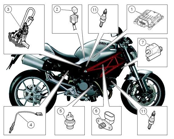
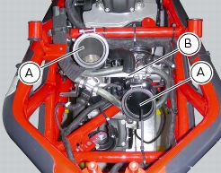
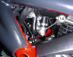
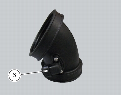
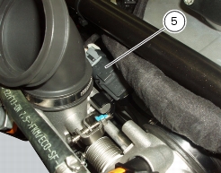
The engine control system (ignition and injection) relies on several sensors which correct mixture strength according to air pressure and temperature and engine load. An air temperature sensor (6) located on the intake manifold of the vertical cylinder and an air pressure sensor (5) located between the “V” of the engine block, connected to the air intakes, measures the atmospheric pressure and transmits this information to the ECU where it used to make essential adjustments to the quantity of fuel injected when the motorcycle is ridden at varying altitudes (e.g. a route that starts at sea level and ends at a high altitude); The ECU also uses this information to adjust the air/fuel ratio according to air density. (Assuming that the volume of air remains constant, an increase in temperature will lead to a decrease in the air density and consequently a reduced oxygen content, whereas a fall in temperature will cause an increase in air density and consequently the oxygen content will rise.
When the ignition switch is turned to ON, the control unit feeds the fuel pump for a few moments to put fuel feed hydraulic circuit under pressure. It receives and processes the throttle position and engine temperature signals. When the engine is started, the unit receives the engine RPM and timing signals that allow it to proceed with injection and ignition. To facilitate start-up, the basic mixture is made richer in accordance with the engine temperature. During starting, the ignition advance is fixed (0°) until the engine starts. When the engine starts, the ECU controls the ignition advance in accordance with the values stored in the map and makes any necessary corrections according to the air and engine temperatures.