|
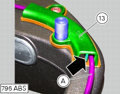
13 -
|
|
2
|
|
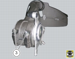
3
|
|
6
|
|
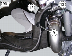
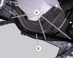
9
|
|
10
|
|
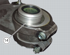
14
|
|
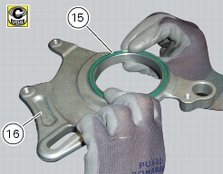
15
|
|
18
|
|
19
|
|
20
|
|
21
|
|
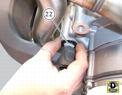
22
|
|
23
|
|
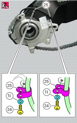
24
|
|
25
|
|
29
|
|
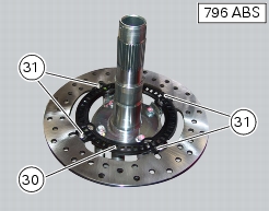
31
|
|
32
|
|
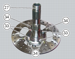
33
|
|
34
|
|
36
|
|
37
|
|
38
|
|
40
|


|
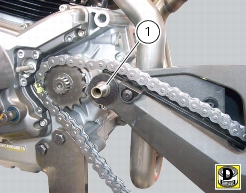
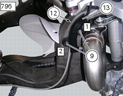
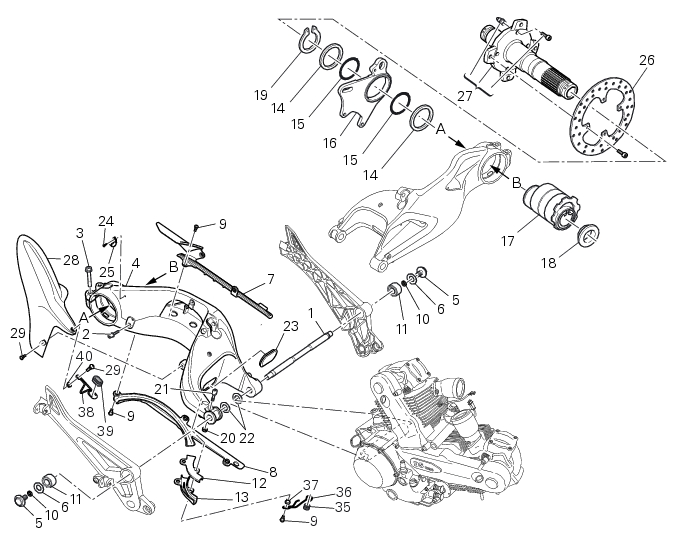
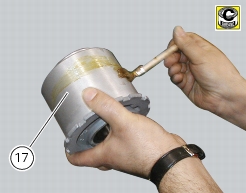
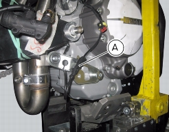
Remove the shock absorber from swinging arm
|
|


|
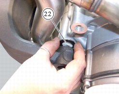
-
|
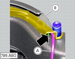
insert a 1.8 mm shim (22) on either side of the engine;
|
|
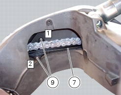
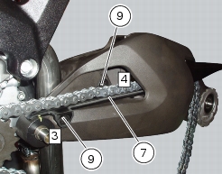
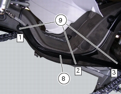
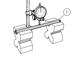
-
|
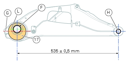
hold the left arm of swingarm (8) against the engine and measure the clearance on the other side of engine using a feeler gauge or calibrated shims.
|
|
1 x 0.10 mm
|
||
|
1 x 0.10 mm
|
1 x 0.10 mm
|
|
|
1 x 0.20 mm
|
1 x 0.20 mm+
1 x 0.1 mm
|