|
7 -
|
|
1
|
|
4
|
|
5
|
|
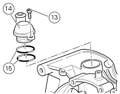
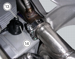
6
|
|
7
|
|
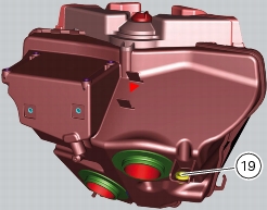
10
|
|
11
|
|
12
|
|
13
|
|
15
|
|
16
|
|
17
|
|
18
|
|
19
|
|
20
|
|
21
|
|
22
|
|
24
|
|
25
|
|
27
|
|
28
|
|
31
|
|
6 - 2, Removal of the battery
|
|


|
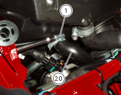
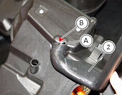
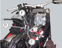
A
|
|
B
|
Solenoid starter (Sect. 6 - 3, Starter contactor);
|
|
C
|
Battery support (Sect. 6 - 2, Battery support);
|
|
D
|
Coils (Sect. 6 - 12, Coil).
|


|
6 - 2, Refitting the battery
|
|