|
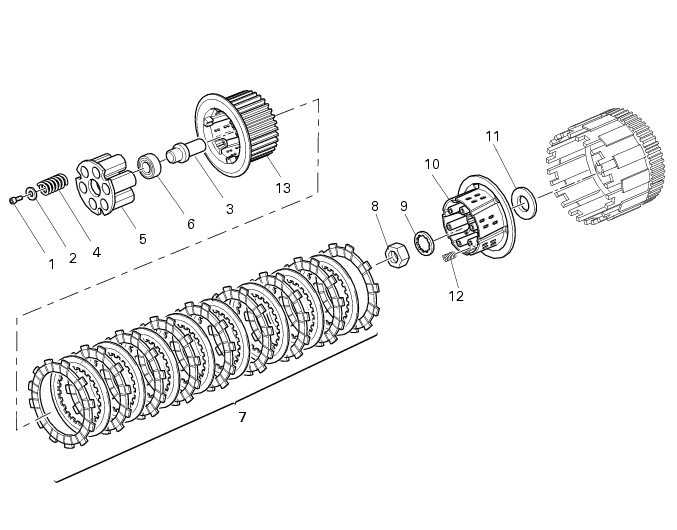
1
|
|
2
|
|
6
|
|
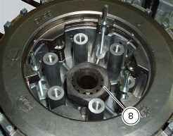
8
|
|
11
|
|
12
|
|
13
|
|
-
|
|
-
|
reduces the amount of driver effort required to disengage the clutch. The clutch lever effort is significantly reduced, without compromising the feel of the lever to the rider (servo-assisted).
|


|
-
|
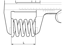
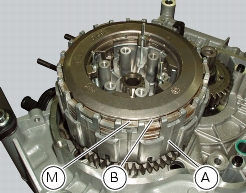
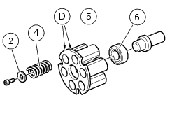
Minimum length: 41 mm.
|