|
1
|
|
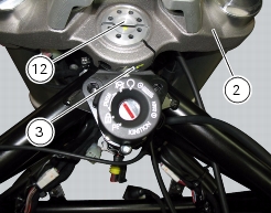
3
|
|
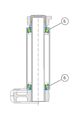
5
|
|
6
|
|
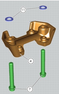
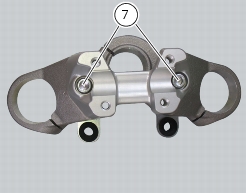
7
|
|
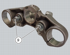
9
|
|
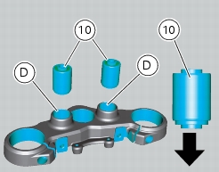
10
|
|
11
|
|
12
|
|
13
|
|
14
|
|
15
|
|
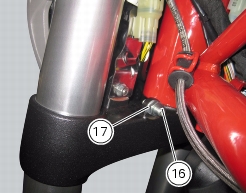
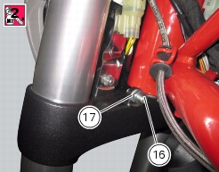
16
|
|
17
|
|
18
|
|
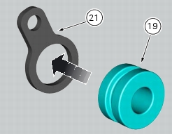
20
|
|
21
|
|
22
|
|
23
|
|
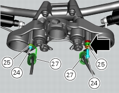
24
|
|
25
|
|
26
|
|
27
|
|
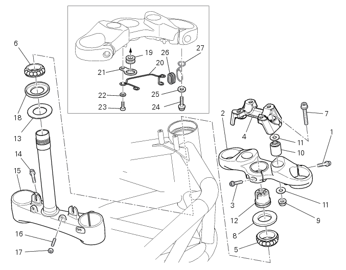
7 - 10.1, Removal of the front forks
|
|
|
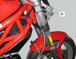
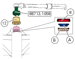
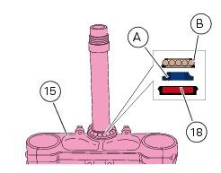
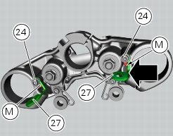
Disassembling the handlebar from the steering head
|


|
-
|
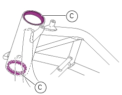
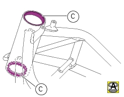
heat the steering head to 150 °C;
|


|
7 - 10.1, Refitting the front forks
|
|
|
Reassembling the handlebar on the steering head
|
7 - 8, Refitting the handlebar
|