|
4
|
|
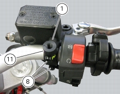
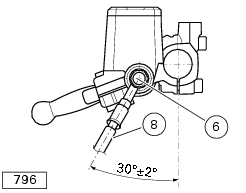
8
|
|
11
|
|
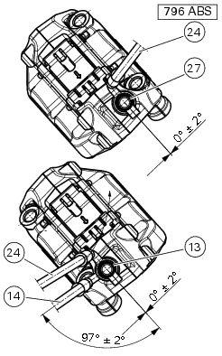
13
|
|
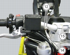
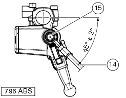
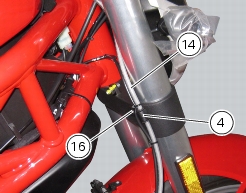
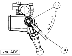
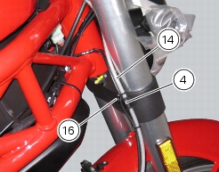
14
|
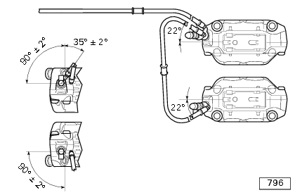
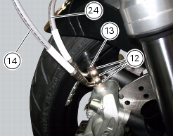
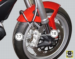
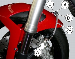
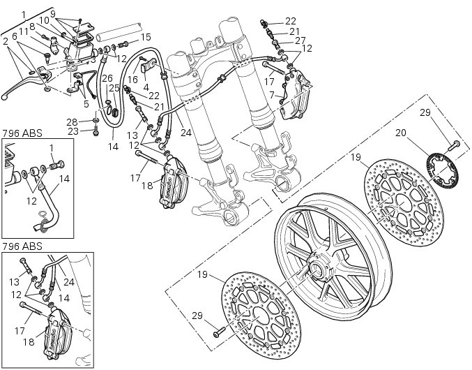
Callipers–master cylinder hose
|
|
15
|
|
16
|
|
17
|
|
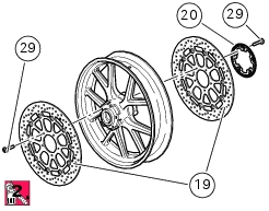
19
|
|
20
|
|
21
|
|
22
|
|
23
|
|
25
|
|
26
|
|
27
|
|
28
|
|
29
|