|
1
|
|
4
|
|
5
|
|
7
|
|
9
|
|
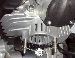
12
|
|
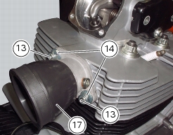
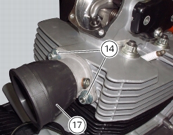
13
|
|
14
|
|
15
|
|
18
|
|
19
|
|
20
|
|
21
|
|
24
|
|
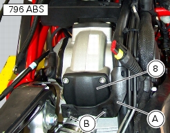
Disconnect ECU connector from main wiring harness
|
|


|
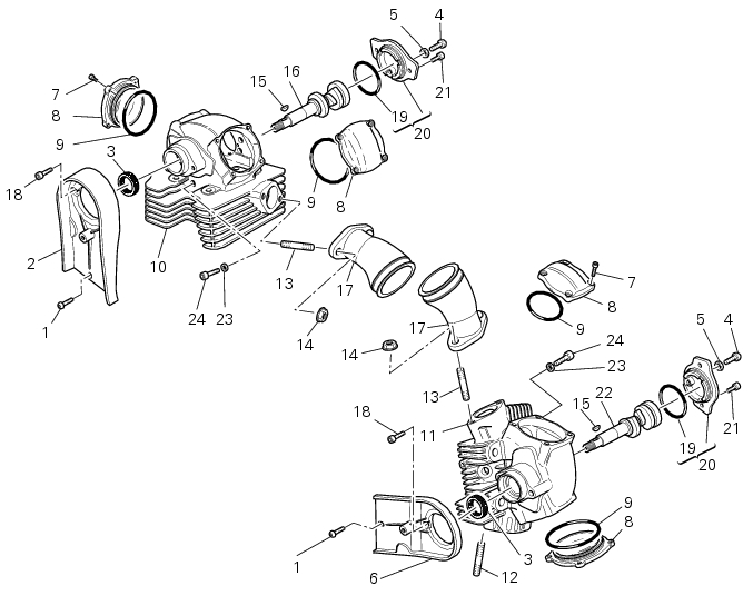
Remove the timing belts and camshaft timing belt pulleys on the heads
|


|
Remove the timing belts and camshaft timing belt pulleys on the heads
|
|


|
-
|
service limit: 0.1 mm.
|


|
Refit the timing belt pulleys on the heads and the timing belts
|
|

|
Refit the camshaft and the timing belt pulleys on the heads
|
|