9.3 -
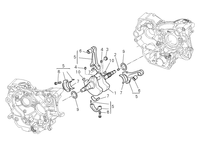
Crankcase assembly: crankshaft/connecting rods assembly
1
Crankshaft
2
Drilled grub screw
3
Plug
4
Grub screw
5
Connecting rod assembly
6
Bush
7
Half bearing
8
Banjo bolt
9
Shim washer
10
Key
Spare parts catalogue
796
CONNECTING RODS
796 ABS
CONNECTING RODS
Important
Bold reference numbers in this section identify parts not shown in the figures alongside the text, but
which can be found in the exploded view diagram.
Removal of the crankshaft/connecting rods assembly
Operations
Section reference
Remove the engine from the frame
9 - 1,
Removal of the engine
Remove the clutch-side crankcase cover
9 - 6.2,
Removal of the clutch cover
Remove the complete clutch assembly
9 - 6.1,
Removal of the APTC clutch
Remove the oil pump
9 - 2.1,
Removal of the oil pump
Remove the primary gear
9 - 6.3,
Removal of the primary drive gear
Remove the alternator-side crankcase
cover
9 - 8,
Removal of the generator cover
Remove the flywheel/alternator assembly
9 - 8,
Removal of the flywheel/alternator assembly
Remove the starter motor idler gear
9 - 9.1,
Removal of the starter motor idler gear
Remove the starter motor
6 - 3,
Removal of the starter motor
Remove the side timing belt covers
9 - 4.2,
Removal of the timing belt covers
Remove the timing belts
9 - 4.2,
Removal of the timing system assembly
Remove the complete cylinder head unit
9 - 4.4,
Removal of the cylinder head assembly
Remove the cylinder barrel/piston
assemblies
9 - 5,
Removal of the cylinder/piston assembly
Remove the mesh filter
4 - 3,
Changing the engine oil and filter cartridge
Separate the crankcase halves
9 - 9.2,
Separation of the crankcase halves
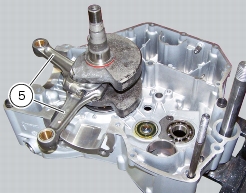
After separating the crankcase halves, withdraw the crankshaft (1) complete with connecting rods (5).
Disassembly of the crankshaft/connecting rods assembly
Unscrew the screws (8) and separate the connecting rods (5) from the crankshaft (1).
Important
Take care not to mix up components of different connecting rods and maintain the original orientation.
Overhaul of the connecting rods
Make the following dimensional checks on the connecting rods:
-
clearance with gudgeon pin on assembly (Sect.
3 - 1.1,
Cylinder/Piston
).
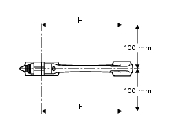
In the event of excessive wear, replace the connecting rod. The small end bushing must be in good condition and firmly driven
into its seat. Check for parallelism error measured at
100
mm from the connecting rod longitudinal axis:
the value must be
H
-
h
less than
0.02
mm; otherwise, renew the connecting rod.
The cylinder head diameter must be within the specified values (Sect.
3 - 1.1,
Cylinder/Piston
).
It is preferable to use crankshafts and connecting rods of the same size class.
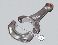
Renewal of the connecting rod bearings
It is good practice to renew the bearings (7) each time the engine is overhauled.
Replacement bearings are supplied ready for assembly and they must not be reworked with scrapers or emery cloth.
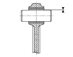
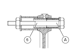
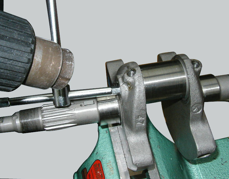
Renewal of the small end bushing
To renew the bushing (6) use the tool shown in figure to simultaneously drive out the old bushing and install the new one (A).
Position the new small-end bushing so that the split is at 90° relative to the upper hole in the small-end.
Drill lubrication holes into the new bushing in correspondence with the existing lubrication holes on the connecting rod small end.
Now ream out the bushing until the inside diameter (D) is
18.006
to
18.024
mm.
Crankshaft overhaul
The main bearing and big-end journals should not be scored or grooved.
The threads, tongue seats, and slots must be in good condition.
Check for fretting or burrs in the fillet between journal and shoulder.
Fillet radius:
1.5
mm.
With the aid of a micrometer, measure the ovality and taper of the big-end journals, taking the measurements in various different
directions (Sect. 3 - 1.1,
Cylinder/Piston
).
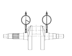
Use a dial gauge to measure the alignment of the main journals by setting the crankshaft between two opposing centres
(Sect. 3 - 1.1,
Cylinder/Piston
).
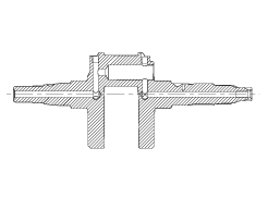
Unscrew all the plugs (4), (3) and (2) from the crankshaft; heating the crankshaft, if necessary, to remove the threadlocker applied
at the time of assembly.
Use a hot air gun that can reach
150
°C.
Clean all the oilways using suitable diameter metal brushes and then blow with compressed air to remove any residues that have
accumulated and are restricting the oil flow.
Apply the recommended threadlocker to the threads of plugs (3), (4) and (2) and refit them.
Tighten the plugs (2) and (4) to a torque of 13 Nm (Min. 11 Nm - Max. 15 Nm) and the plug (2) to a torque of 15 Nm (Min. 13.5
Nm - Max. 16.5 Nm) (Sect. 3 - 3,
Engine torque settings
).
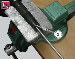
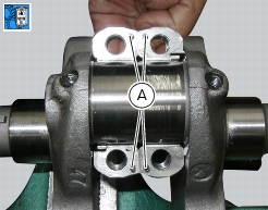
Big-end bearing shell-journal clearance
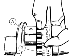
To check the assembly clearance between the bearing shells and crankshaft journals you will lay a strip (A) of GREEN
“Plastigage PG-1” on the journal.
Fit the connecting rod with the original big-end bearing shells (7) (see procedure on next page) and tighten the screws (
8
) to a torque of
49
Nm.
Remove the connecting rod and compare the thickness of the Plastigage strip to the scale (B).
If the width measured corresponding to the existing clearance is not within the prescribed limit (Big-end bearing-to-crankpin
clearance paragraph under Sect. 3 - 1.1,
Cylinder/Piston
), either the bearings or the crankshaft must be replaced.
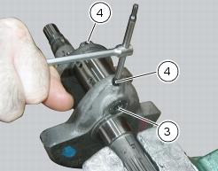
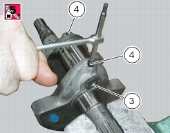
Reassembly of the connecting rods
Before starting, check that the crankshaft main bearing journals and big-end journals are free of burrs or evident signs of
machining: if necessary, clean the surfaces with very fine emery cloth and oil.
Check that the grooves are in perfect condition with no signs of forcing.
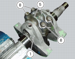
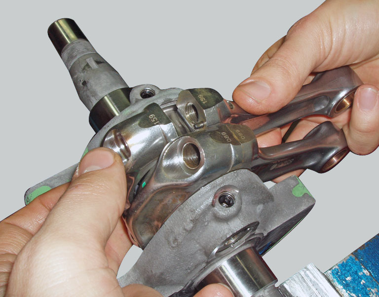
Check that each connecting rod and cap are equipped with their locating pins (A).
Wash the pins and dry them with compressed air.
Clean and lubricate the journals and con-rod bearing shells with engine oil and fit the con-rods in their original mounting positions.
Fit the caps to the corresponding connecting rods. Make sure that the mark on the cap is the on the same side as the mark on
the connecting rod.
Use the recommended grease to lubricate the threads and underside of the heads of the new screws (8) and the threaded hole
in the connecting rod, packing in grease from both sides of the hole.
Warning
The grease utilised is an irritant in contact with the skin. Wear protective gloves.
Important
Lubrication of big-end cap screws is essential to obtain the correct coupling and to prevent breakage of the parts.
The big-end cap screws may only be used for
one tightening
.
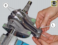
Temporarily fit the gudgeon pin (L) to align the connecting rods, and then tighten the screws.
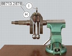
Fit the spacer (H) of the tool
88713.2878
between the connecting rods and take up residual axial clearance with the fork feeler gauge (I) of the tool
88713.2878
which is available in the following thicknesses:
-
0.1
mm -
0.2
mm -
0.3
mm.
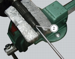
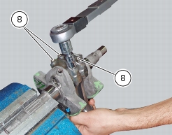
Use the torque wrench, as shown in the picture, to tighten the screws (8) to the torque here below (Sect. 3 - 3,
Engine torque settings
):
-
tighten to a torque of 35 Nm;
-
wait 2 seconds and then back off through 360°;
-
initial tightening to 20 Nm;
-
tightening to 35 Nm;
-
tightening to 65 ±1
-
torque check 70 to 103 Nm.
Withdraw the feeler gauge and check that the connecting rod/crankshaft end float is:
0.15
to
0.35
mm.
Refitting the crankshaft/connecting rod assembly
Install the connecting rod assembly in the crankcase half, carry out the shimming procedure as described in Sect.
9 - 9.2,
Shimming the shafts
.
Important
Make sure that the connecting rods (5) are correctly positioned in the respective cylinder seats. Incorrect positioning of the
connecting rods at this stage will inevitably lead to the need to re-open the crankcase halves.
Operations
Section reference
Reassemble the engine crankcase halves
9 - 9.2,
Reassembly of the crankcase halves
Refit the mesh filter
4 - 3,
Changing the engine oil and filter cartridge
Refit the cylinder barrel/piston assemblies
9 - 5,
Refitting the cylinder/piston assembly
Refit the complete cylinder head unit
9 - 4.4,
Refitting the cylinder head assembly
Refit the timing belts
9 - 4.2,
Refitting the timing system assembly
Refit the timing covers
9 - 4.2,
Refitting the timing belt covers
Refit the starter motor
6 - 3,
Refitting the starter motor
Refit the starter motor idler gear
9 - 9.1,
Refitting the starter motor gear
Refit the flywheel/alternator assembly
9 - 8,
Refitting the flywheel-alternator assembly
Refit the alternator-side crankcase cover
9 - 8,
Refitting the generator cover
Refit the primary gear
9 - 6.3,
Refitting the primary drive gears and checking backlash
Refit the oil pump
9 - 2.1,
Refitting the oil pump
Refit the clutch assembly
9 - 6.1,
Refitting the APTC clutch
Refit the clutch-side crankcase cover
9 - 6.2,
Refitting the clutch cover
Refit the engine to the frame
9 - 1,
Refitting the engine